DIY Wireless Timer
Basic single lane Radio Timer
Components
From www.Netairbuy.com (contact Gao) now at www.carymart.com
1 x Single channel Wireless Garage door controller
2 x CB-1 long range transmitters
from electronic parts suppliers
Boxes
AA battery holders - 2 x 9volt and 1 x 12volt
2 x 9 volt batteries
20 x AA batteries
3 x Switches
2 5V SPST Dil Reed Relay, or 2 x PRMA1a12 reed relays
2 x Resistors
2 x Capacitors
RJ11 plugs and sockets wires
4 strand or 2 strand telephone lead.
1 x BTS Timer Which you can order directly from BTS Here
or if you must, a DIY modified Electronic stopwatch (this is very tricky for most!)
2 x Tape switches – Greg Ambler pattern – see How to build a Tape Switch here......
Step 1 get a BTS Timer, and you can proceed directly to Step 2!
But if you are too cheap or too poor, or have too much fear of anything imported to your fair land, to get a BTS timer....read on.
Open up your imported stop watch, and locate the stop start switch.
Strip back two of the wires in a short length of 4 strand telephone lead.
Solder the wires to each contact of the stop/start switch.
On the other end of the lead, fit a rj12 connector so that the two wires soldered to the stop watch switch are the centre two leads in the rj12 connector.
(BTS Tape switches and timer also use the centre two wires in the rj12 connectors)
File a little of the watch case so that the telephone cable can pass through the case, but also be firmly held (clamped) in place when the case is shut.
Re assemble the Stopwatch.
(BTS Timer will save you all of that effort, and it works perfectly with this system)
Step 2 – mount the receiver
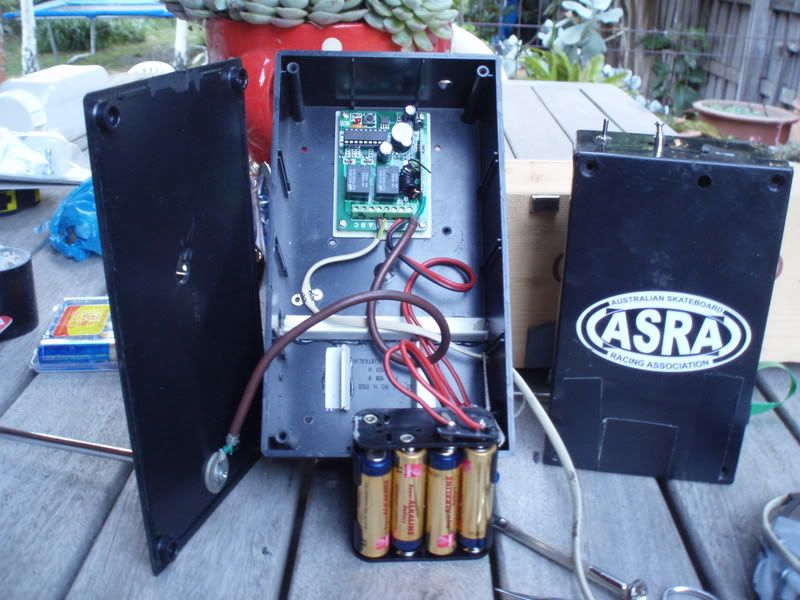
Mount the wireless receiver in a box with an 8 x AA battery holder (12 volt s), and on/off switch.
Set the transmitter to momentary operation.
Connect a telephone cable to the relay contacts, and on the other end, using an rj 12 connector, and a female to female rj12 adaptor, join that to the stopwatch cable.
Use one of the transmitters to check that the receiver works, and the stopwatch starts and stops each time you press the transmitter button.
Step 3 – make a delay circuit
Because the front wheel of the skateboard, crossing the tape switch will start the timer, and the back wheels will then stop the timer, we need to delay the closed state of the tape switch long enough for the rear wheels to cross the tape switch, so that the timer runs until the front wheels cross the tape switch at the finish of the course. (and also so that the transmitter stays on long enough to trigger the receiver.) This only needs a delay of about 2 seconds.
Using a reed relay as a simple "delay" switch.
The delay circuit consists of a 9volt battery, a capacitor, a reed relay, and a resistor.
A relay has 4 terminals, being 2 for the magnetic solenoid coil, and two for switching. When the coil of a relay is charged, it pulls the switch from an open switch (non-conductor) to a closed switch (conductor). By using a capacitor and a resistor you can keep the coil of the relay charged for a period of time, after the power is disconnected from the circuit.
Assemble delay circuit
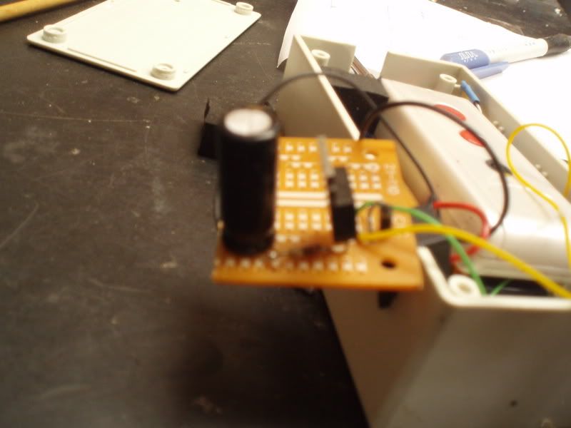
The positive terminal of a 9 volt battery is connected to the capacitor via the tape-switch, The positive terminal of the capacitor is then connected to the coil terminal of the relay via a resistor. When the tape switch is crossed, the battery fills the capacitor instantly, which is slowly discharged via the resistor, into the solenoid coil of the relay. The negative terminals of the capacitor and battery are connected to the other side of the solenoid coil, ie circuit ground. Next join leads to the relay switching circuit. These two leads run to the radio transmitter switch.
Exact size and value of resistor and capacitor is determined by the delay that you need, and you can find out suitable values from most electronics books.
Step 4 Modify the transmitter.
Open the transmitter case, and locate the activation switch on the circuit board. Solder the two leads from the delay circuit to the contacts from the switch. (I used rj12 socket and plug to join the delay circuit to the on switch on the transmitter) Connect the tape switch to the delay circuit and test. The transmitter should stay on for a few seconds.
Next connect the 6 x aa (9volt) battery holder, via some leads and a switch to the battery contacts in the transmitter.
Step 5 Assemble transmitter boxes.
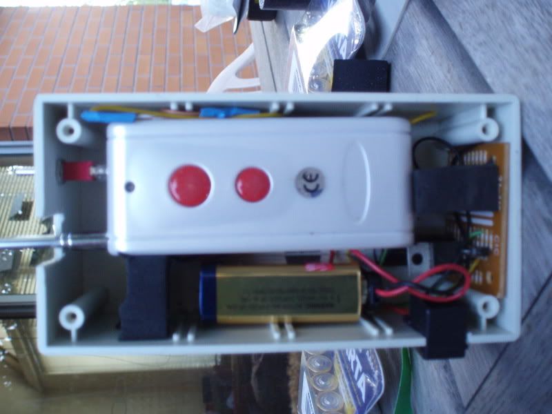
Put the delay circuit and its battery into the box, with a rj12 female socket set into the side of the case. This socket connects the tape-switch to the battery and the capacitor in the delay circuit, using centre two connectors.
Hold components in place with double sided tape.
Connect the delay circuit leads to the transmitter, and put the transmitter and its battery into the case. Then test and close the case.
(note that the transmitter shown is not the CB-1 transmitter, and is using a single 9volt battery for the delay circuit, and another 9 volt battery, mounted behind the transmitter for transmitter power)
Step 6 - set it up and use it
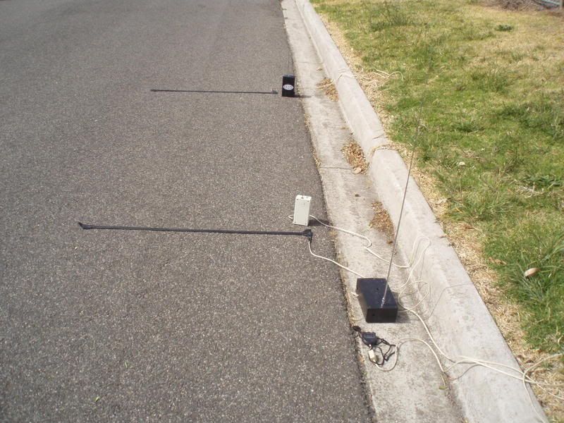
Connect the tape switches, turn everything on, and start racing.
AA batteries give much better duration than the 9volt batteries for the transmitter, and should last about 20 or 30 sessions (guessing, have not run flat yet!).
This setup is good for about 120 metres in a ditch, and about 200 metres in open ground.
The best part is the portability and simplicity of use, with no cables to trip over.
Cost should be under $100 for the wireless link.
I used a dual channel controller, for this set-up but unfortunately it does not work for twin lane racing, as the second channel to trigger has to wait until the first channel has stopped receiving. For twin land racing it is best to use two single channel receivers and 4 transmitters.
Views: 1788
Replies to This Discussion
-
ASRA AdminPermalink Reply by bernie on -
Steve, Go ahead, share the joy!
Also put the link to your post on the Fish in this thread so that Gao can follow it to the USA site, and pick up some of the feedback.
I have sent a link to this thread, to Gao at netairbuy, to see if I can get him interested in building the delay circuit and the rj12 connector into the CB-1 transmitters. If he can do that all we need to do is make our own tape switches, and modified stopwatches.
-
ASRA AdminPermalink Reply by Bugs on -
Bernie, if you create a blog post with the same content, I'll put it on the front page. Just make sure you have one image as the first thing in the post.
This is gold.
-
Permalink Reply by SteveC on
-
This certainly is gold.
On the fish I simply made links to this page and one to the switches.
The fish-thread is here.
-
ASRA AdminPermalink Reply by bernie on -
Reply received from netairbuy.
Hello,
I saw your project, it is a very good device.
If someone can order in bulk, we will can produce them.
Regards,
Gao
So now we need to find out how many are needed!
-
Permalink Reply by Traveler on
-
I have a Trakmate system, would I be able to adapt this set up by using only the garage switch and the CB transmitters? totally cool set up by the way! thanks.
-
ASRA AdminPermalink Reply by bernie on -
You could use it to replace the cables, but you will probably need one 2 channel receiver for each lane, so that you can have the start gates on channel 1, and finish gate on channel 2 for each lane, and you will need 1 delay circuit for each tape switch.
So use 2 x two channel unit shown in what I have built. You should be able to mount both receivers in the one box, running off the same battery.
One note on range. It has better range when the transmitters and receiver are more than 1 metre above ground, but don't count on getting 300 metres all the time. If there are lots of powerlines in the area, or trees and people between transmitter and receiver, then range is reduced.
You can increase range by having the receiver at the mid point of the course. Mostly we have been using it on short courses, ie approx. 100 metres.
Someone also asked about accuracy.
With any wireless system, there will be a delay between crossing the tape, getting the signal out, receiving the signal, decoding the signal and then closing the relay, to stop the clock, that does not exist in a cable system. Electrons and radio waves travel at the speed of light, but as for decoding signals and closing relays who knows, but my guess is that it is less than 100th of a second.... Providing that there is a radio connection at the start and finish tape switch, with the same built in reaction time, the elapsed time recorded between each tape switch should be comparable to a cable system. (which is another good reason for one receiver per lane).
Don't forget that this is a system that costs under $100, and is really designed for training runs, and single lane ditch sessions where running cables is not always that easy (or public car parks where a fast getaway might be needed!). For dual lane racing, something like a Trackmate is preferred.
-
Permalink Reply by Kat Bolina on
-
How do you get the data from the timer? Is it possible to connect it to a software which automatically analyzes the data or present it in ecxel form?
-
ASRA AdminPermalink Reply by bernie on -
Kat, the timer part is only a simple stop watch. Unfortunately it does not link to a computer. It is also best for short courses.
-
ASRA AdminPermalink Reply by bernie on -
Kat,
Have a look at this link http://www.skateboardracing.org.au/forum/topics/chronocone-timing-s...
Software is at http://www.skateboardracing.org.au/profiles/blogs/chronocone46a-1
The modern Game controller hardware turned out to be unreliable, in that it was sending random stops, possibly from line capacitance or some other witchcraft.
If you could get a older style game controller that was less sensitive, like what Pat Chewning originally used, then it should work.
-
-
I think that is very good and like the product.
If some guys need the same thing maybe be go to www.nasasafe.com
© 2026 Created by Bugs.
Powered by
![]()